How to Write an LLVM Backend #4: Instruction Selection
We previously provided a brief overview of the compilation process in the LLVM backend. In this post, we will take a closer look at the first stage of that process: instruction selection. The aim is to understand how this works and how we can configure it before we look at the concrete implementation of our RISCW backend.
NOTE: The LLVM documentation has this short and clear explanation of how instruction selection works, so this post is mostly a re-statement of that enhanced with examples.
NOTE: The examples shown in this post are constructed using our skeleton RISCW backend. The source for that can be found here.
NOTE: Posts in this series:
- Introduction
- Getting Started
- Setting Up a New Backend
- Configuring the Build System
- Instruction Selection
- Arithmetic Instructions
The instruction selection process takes as an input the LLVM IR and outputs a sequence of instructions that use an infinite set of registers. The process is split into the following phases:
- Build initial DAG
- Optimize
- Legalize types
- Optimize
- Legalize operations
- Optimize
- Target instruction selection
- Scheduling and formation
I think it is easier to learn whats happening by following an example. So we
will consider how the simple C program below is transformed as instruction
selection proceeds. The code has a function MUL that takes in a 64-bit argument
x and a 32-bit one y. The arguments are multiplied and a 32-bit integer
result is returned.
unsigned int MUL(unsigned long long int x, unsigned int y)
{
    return x * y;
}
Build DAG Phase
This is the first phase of instruction selection. It takes an LLVM IR as an input and produces a Selection Directed Acyclic Graph (DAG) as an output. Every other phase in the instruction selection process operates on the DAG until the output instruction sequence is emitted. As discussed a few posts ago, the LLVM IR is generated from the C code by a front-end tool, like Clang, and later optimized by the LLVM optimizer. Here is the LLVM IR for our simple C program:
define dso_local i32 @MUL(i64 %x, i32 %y) local_unnamed_addr #0 {
entry:
  %0 = trunc i64 %x to i32
  %conv1 = mul i32 %0, %y
  ret i32 %conv1
}
The Selection DAG is effectively a fancy tree data structure that represents a
basic block in the LLVM IR. A basic
block is a sequence of instructions
without branch destinations (except the entry) and no branch instructions
(except the exit). Our example MUL function is simple enough that it only has
one basic block called entry, but other functions typically have
multiple basic blocks. For instance, the hello function below has four basic
blocks: entry, if.then, if.else and return. Each basic block will be
translated to a separate DAG.
define dso_local i32 @hello(i32 %x) local_unnamed_addr #0 {
entry:
  %cmp = icmp eq i32 %x, 100
  br i1 %cmp, label %if.then, label %if.else

if.then:                                          ; preds = %entry
  %call = tail call i32 bitcast (i32 (...)* @hello100 to i32 (i32)*)(i32 100) #2
  br label %return

if.else:                                          ; preds = %entry
  %call1 = tail call i32 bitcast (i32 (...)* @helloOther to i32 (i32)*)(i32 %x) #2
  br label %return

return:                                           ; preds = %if.else, %if.then
  %retval.0 = phi i32 [ %call, %if.then ], [ %call1, %if.else ]
  ret i32 %retval.0
}
A Selection DAG has the following properties:
- Each node is an instance of the
SDNodeclass representing an operation, like add, subtract, multiply, etc. The operation types are ininclude/llvm/CodeGen/ISDOpcodes.h. - Each node has 0 or more input operands, which are outgoing edges to the node
defining the used value. Edges are instances of the
SDValueclass. - Values produced by the operations in a node have a Machine Value Type
(MTV). Examples of types are
i1andi8which represent 1- and 8-bit integer values respectively. - Nodes that have side-effects force an ordering on operations, e.g return
statements and loads, so they have a special chain value of type
MVT::Otheras both an input operand and an output. - A leaf node of type
ISD::EntryTokenis the designated entry into the code. - The root node of the DAG is the final side-effecting node with a chain operand. This is the last operation performed in the block of code represented by the DAG, such as a return at the end of a function.
WARNING! The type system in the LLVM backend is VERY limited. A lot of
useful type information is thrown away when the input LLVM IR is converted to a
DAG. Perhaps the most notable omission are pointer types which are completely
absent from the list of types in the
MVT
class. As a result, pointers have integer type in the DAG, so it is difficult
to tell whether a node, like an add, has integer or pointer operands.
Here is the initial Selection DAG that I get from the MUL function.
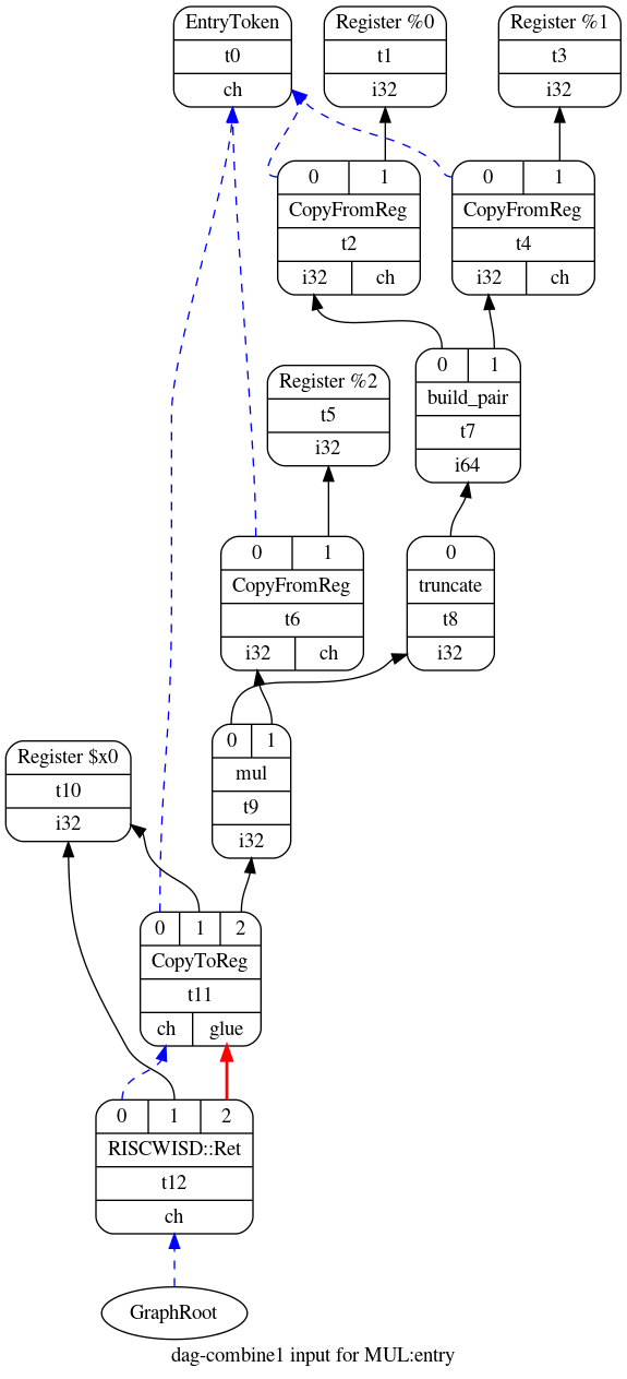
The entry node is at the top of the image while the root of the DAG is at the bottom. There is also a chain of nodes joined with blue edges starting from the root and ending on the entry node. These blue edges are the chain operands discussed earlier. In contrast, the black edges show the flow of data values such as integers and floating-point numbers. An equivalent text representation of this Selection DAG is shown below:
t0: ch = EntryToken
        t2: i32,ch = CopyFromReg t0, Register:i32 %0
        t4: i32,ch = CopyFromReg t0, Register:i32 %1
      t7: i64 = build_pair t2, t4
    t8: i32 = truncate t7
    t6: i32,ch = CopyFromReg t0, Register:i32 %2
  t9: i32 = mul t8, t6
t11: ch,glue = CopyToReg t0, Register:i32 $x0, t9
t12: ch = RISCWISD::Ret t11, Register:i32 $x0, t11:1
NOTE: A Selection DAG may contain target-independent and target-specific
operation nodes. Target-independent operations are defined in
ISDOpcodes.h
as mentioned above. Target-specific operations are defined by each backend,
typically in the same file that declares the target’s TargetLowering subclass.
You can find the target-specific nodes for RISCW in
llvm/lib/Target/RISCW/RISCWISelLowering.h.
The Selection DAG shown above for MUL has a node t12 with the target-specific
operation RISCWISD::Ret that represents the return from the function.
NOTE: You can tell LLVM to generate a visual representation of the
Selection DAG at various stages of the instruction selection process by passing
-view-dag-combine1-dags, -view-legalize-dags, -view-dag-combine2-dags,
-view-isel-dags or -view-sched-dags as command line arguments when invoking
llc. The -debug argument tells llc to generate a text representation of
the Selection DAG.
Optimization Phase
There are three optimization phases during the instruction selection process. The first optimization pass is applied immediately after the Selection DAG is constructed from the LLVM IR. The remaining two passes are applied after the legalization phases. According to the LLVM documentation, these optimization phases are meant to simplify unnecessarily complex Selection DAGs that may have been produced by other phases, like legalization.
As far as I can tell, these optimization phases are limited to running a
compilation pass that combines groups of nodes into simpler
nodes. To achieve this, LLVM has this huge C++
file
(>20,000 lines) that traverses the DAG and uses pattern matching on the nodes
to identify and apply optimization opportunities. For example, the combiner
could convert the nodes (add (add x, y), z) from the input Selection DAG into
(add x, y+z) thus eliminated an add node.
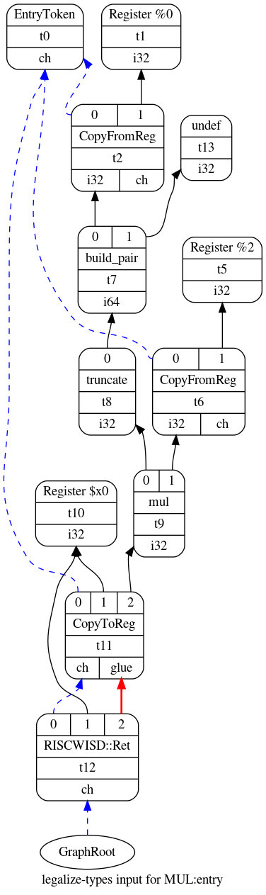
The output Selection DAG of the first optimization pass is shown in the figure
below for our example MUL function. Compared to the Selection DAG from the
previous section, the optimized DAG contains the node t13 instead of nodes
t3 and t4. The combiner was able to perform this optimization, which
discards the most significant 32 bits of the 64-bit function argument x,
because the multiplication in the function body and the return argument rely on
32-bit integers. Therefore, the DAG can be simplified by eliminating t3 and
t4.
LLVM’s DAG combiner only optimizes target-independent operation nodes, i.e.
those defined in
ISDOpcodes.h
like add, sub, load and store. Backends can provide additional combiner
functionality for target-independent and target-specific nodes by overriding
the
PerformDAGCombine
hook in their TargetLowering subclass. Also, the backend has to specify the
target-independent nodes that it wishes to be notified of during an
optimization phase by calling
setTargetDAGCombine
in the constructor of their TargetLowering subclass.
NOTE: Confusingly, the TargetLowering subclass of an LLVM backend is
usually implemented in the <TARGET_NAME>ISelLowering.cpp file. You can find
the RISCW one in llvm/lib/Target/RISCW/RISCWISelLowering.cpp.
NOTE: The XCore backend has a good example –and by good I mean
easy-to-read– for using PerformDAGCombine and setTargetDAGCombine (see
here
and
here).
Also, take a look here to see how that backend combines the nodes
add(add(mul(x, y), a), b) into the simpler target-specific lmul(x, y, a, b)
node as the XCore architecture has a long multiply-accumulate instruction.1
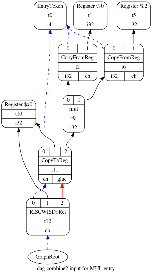
Legalize Types and Legalize Operations Phases
The optimized DAG shown above contains a node t7 that produces a 64-bit
value of type i64, but the RISCW machine is only 32-bit. The legalize phases
take care of these problems.
The legalize types phase is run first. It converts the DAG to only use data
types natively supported by the machine. To achieve this, it converts, or
promotes, small types to larger ones; for example, a 1-bit integer of type
i1 is converted to a 32-bit integer of type i32. Also the compiler breaks
up, or expands, large integers into smaller ones, such as 64-bit integers of
type i64 that are converted into 32-bit integers of type i32 in a 32-bit
machine. The DAG below is a legalized version, with regards to types, of the
optimized DAG shown before for the MUL function. In this case, the compiler
decided to eliminate the t3 and t7 nodes to ensure that the new DAG only
uses i32 integers.
The legalize operations phase is run after the second optimization phase. It
converts the DAG to only use operations supported by the machine. For example,
a DAG may contain bit-rotate left (rotl) nodes, but the target instruction
set might not have that instruction. Thus, the operation needs to be
implemented with a combination of bit shifts and ors; the legalize operations
phase implements such changes to the DAG.
There are three strategies to legalize operations. First, the compiler can expand an unsupported operation into an alternative set of supported operations that emulate the required functionality. Second, a type can be promoted to a larger type that supports the missing operation. And third, the target can use a hook in its TargetLowering subclass to implement a custom legalization in C++.
NOTE: In future posts, I will explain how a backend can configure the legalization phases; this can be done in the constructor of the target’s TargetLowering subclass.
Target Instruction Selection Phase
At this point, the DAG mostly contain nodes with target-independent
operations, like add and subtract, along with a few target-specific operations,
like RISCWISD::Ret. So we need to map these ‘abstract’ operations to concrete
machine instructions from our target architecture; LLVM takes care of this in
the instruction selection phase. The idea is fairly simple: the compiler
pattern matches the nodes in the DAG to machine instructions. The patterns and
descriptions of the instructions are provided by the developer of the compiler
backend via code written in
TableGen. Also, more complex
pattern matching that is difficult to express using TableGen can be coded
directly in C++.
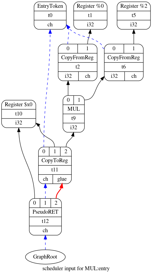
We will look at TableGen more closely in future posts. For now, let us consider
how LLVM matched the legalized and optimized DAG for MUL function to the new
DAG shown below. In this case, only two nodes needed changes. t9 had its
mul operation replaced with the instruction MUL while t12 had
RISCWISD::Ret replaced with the instruction PseudoRET.
Scheduling and Formation Phase
Thankfully, there is not much to say here as the post was getting quite long!
This phase turns the DAG into a list of instructions according to some target
constraints. For example, the target can specify its scheduling preference by
calling
setSchedulingPreference
from the constructor of its TargetLowering subclass.
WARNING! Make sure you experiment with various scheduling preferences! Choosing the wrong one can significantly degrade the emitted code if the scheduling strategy does not match the features of your architecture and processor. The various scheduling options are listed here.
Below is the emited list of instructions for our MUL program. There are a
couple of important things to note. First, the emitted code is still using an
infinite set of virtual registers as opposed to actual machine registers; the
compiler takes care of this problem later with register
allocation. And second,
there is already some liveness information that is useful for the register
allocation process; for example, there are two registers, i.e. x0 and x2,
which are live at the start of the basic block.
bb.0.entry:
  liveins: $x0, $x2
  %2:gpr = COPY $x2
  %0:gpr = COPY $x0
  %3:gpr = MUL %0:gpr, %2:gpr
  $x0 = COPY %3:gpr
  PseudoRET implicit $x0